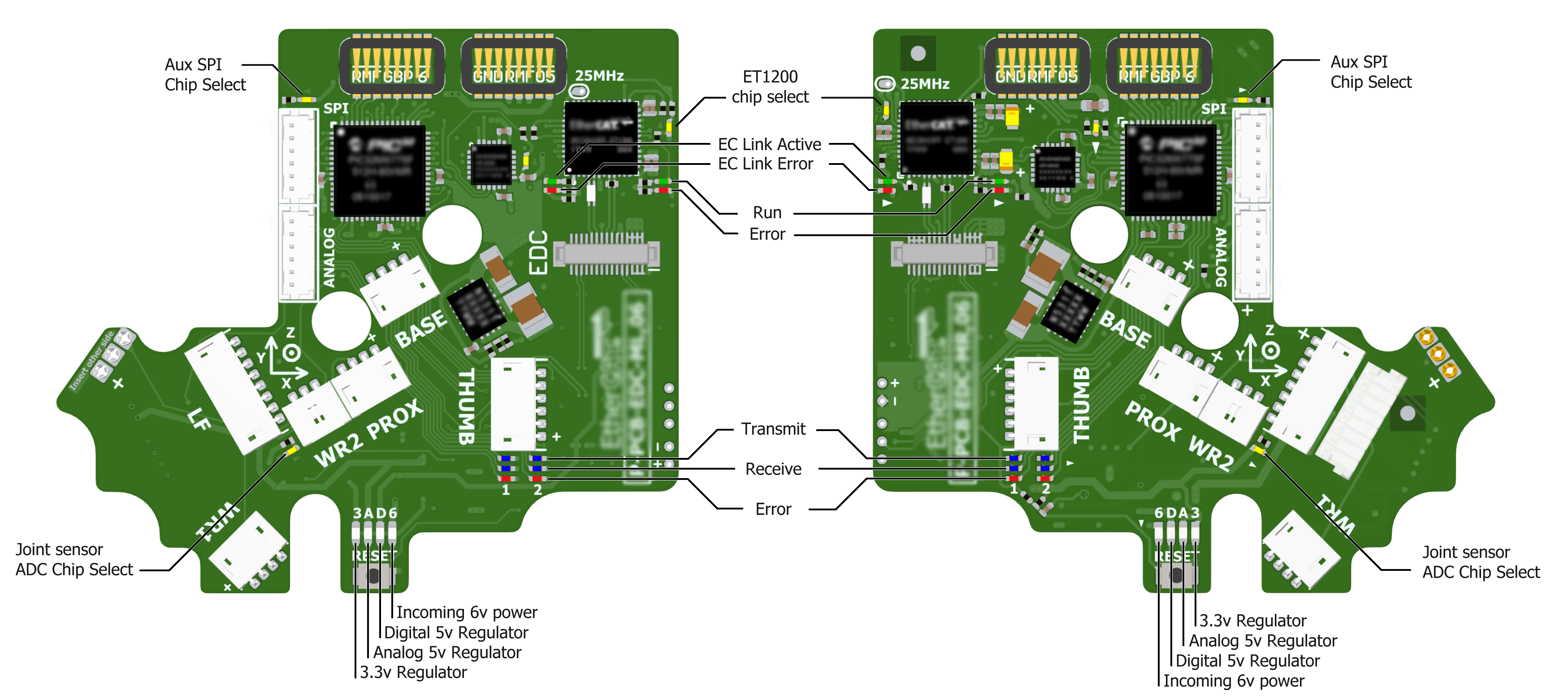
Lights on the hand
Here is an annotation of the back of the hand’s lights:

On power up, the lights will be in the following state:
Item |
Color |
Activity |
Meaning |
|---|---|---|---|
6V Power (Power LED) |
White |
On |
Power good |
A 5V regulator (Power LED) |
White |
On |
Power good |
D 5V regulator (Power LED) |
White |
On |
Power good |
3.3V Regulator (Power LED) |
White |
On |
Power good |
EC Link Active |
Green |
On |
EtherCAT link established |
EC Link Error |
Red |
Off |
No EtherCAT link error |
Run |
Green |
Off |
Hand is in Init state |
Error (Application Layer) |
Red |
On (during boot) |
Verifying ET1200 EEPROM |
Error (Application Layer) |
Red |
Then off |
No EtherCAT packet error |
ET1200 chip select |
Yellow |
On |
PIC32 communicating with ET1200 |
Lights will also appear inside the base, indicating 5v, 6v and 24v (or 28v) supplies. These can only be seen by removing the covers.
When the ROS driver is running you should see the following lights on the Palm:
Light |
Colour |
Activity |
Meaning |
|---|---|---|---|
Run |
Green |
On |
Hand is in Operational state |
Transmit (CAN1/2) |
Blue |
V.fast flicker |
Demand values are being sent to the motors |
Receive (CAN1/2) |
Blue |
V.fast flicker |
Motors are sending sensor data |
Joint sensor ADC chip select |
Yellow |
On |
Sensors being sampled |
After killing the driver, the lights will be in a new state:
Light |
Colour |
Activity |
Meaning |
|---|---|---|---|
Run |
Green |
Blinking |
Hand is in Pre-Operational state |
Transmit (CAN1/2) |
Blue |
Off |
No messages transmitted on CAN 1/2 |
Receive (CAN1/2) |
Blue |
Off |
No messages received on CAN 1/2 |
Joint sensor ADC chip select |
Yellow |
Off |
Sensors not being sampled |